.png)


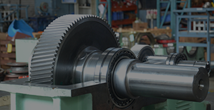
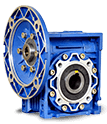
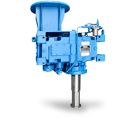
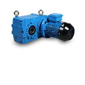
 Standard Worm Gearbox
 Standard Worm Gearbox
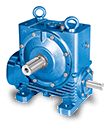
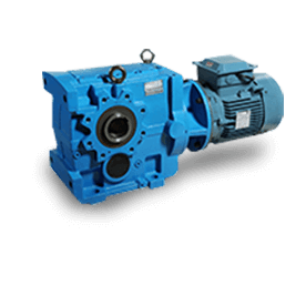
 Special Worm Gearbox
 Special Worm Gearbox
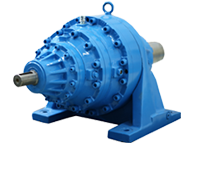
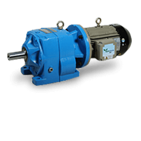
 Modular Worm Gearbox
 Modular Worm Gearbox

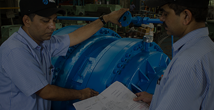
FAQs
For the selection of a suitable worm gearbox, the following data is required:
- Type of prime mover
- Horsepower of prime mover
- Output torque required from driven member
- Input speed of gear unit
- Output speed of gear unit
- Configuration of drive required and shaft disposition.
- Total daily hours of running. If running is intermittent, details of duty cycle should be given. Particulars of any abnormal starting load should be stated.
- Details of reversing or shock loads.
- Details of any external loads imposed on gear unit.
- Details of any abnormal operating conditions, e.g. ambient temperature, humidity, etc.
The mechanical service factor for a gear reducer is decided based on the following parameters:
- Prime Mover – Electric Motor, IC engines, etc.,
- Duration of service hours per day
- Type of load – Uniform, Moderate, Heavy based on the application
Backlash is the free-play between input shaft and output shaft and is typically caused by movement of gear teeth back and forth within tooth spaces.
The location of the output shaft of a reducer relative to its input shaft is called the configurations hand. If you stand facing the input shaft and the location of the output shaft is on the right side this is considered as “R” handing. Similarly, if the location of the output shaft is on the left side this is considered as “L” handing.
A worm gear set is said to be self-locking or irreversible when the worm wheel cannot drive the worm shaft. This condition is obtained if the lead angle of the worm is less than the friction angle, and as a consequence, the efficiency for reversed driving is zero.
The standard maximum allowable oil sump temperature is 95°C as per ANSI/AGMA standard. It must be recognized that operating above 95°C may reduce lubricant and contact seal life and increase the surface deterioration on the gears and bearings, with a subsequent increase in the frequency of maintenance.
The maximum allowable vibration limit for a gear reducer is 75 microns.
The maximum allowable vibration limit for a gear reducer is 85 dB at a distance of 1 meter.
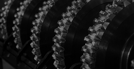
 Modular Helical
 Modular Helical
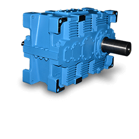
 Standard Helical
 Standard Helical
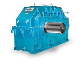
 Special Helical
 Special Helical
FAQs
The following information needs to be given in your enquiry for selection of suitable size of a helical gearbox.
- Type of prime mover
- Horsepower of prime mover
- Output torque required from driven member
- Input speed of gear unit
- Output speed of gear unit
- Configuration of drive required and shaft disposition.
- Total daily hours of running. If running is intermittent, details of duty cycle should be given. Particulars of any abnormal starting load should be stated.
- Details of reversing or shock loads.
- Details of any external loads imposed on gear unit.
- Details of any abnormal operating conditions, e.g. ambient temperature, humidity, etc.
The mechanical service factor for a gearbox is decided based on following parameters:
- Prime Mover – Electric Motor, IC engines, etc.,
- Duration of service hours per day
- Type of load – Uniform, Moderate, Heavy based on the application
The thermal service factor is based on following 2 parameters:
- Ambient temperature
- Running time in any hour.
Some of the advantages of hardened and ground gears are:
- Less noise
- Maximized Efficiency
- Higher Load Capacity
- Correction of Profile
Backlash is the free-play between input shaft and output shaft and is typically caused by movement of gear teeth back and forth within tooth spaces.
The standard maximum allowable oil sump temperature is 95°C as per ANSI/AGMA standard. It must be recognized that operating above 95°C may reduce lubricant and contact seal life and increase the surface deterioration on the gears and bearings with a subsequent increase in the frequency of maintenance.
The maximum allowable vibration limit for a helical gearbox is 75 microns.
The maximum allowable vibration limit for a gear reducer is 85 dB at a distance of 1 meter.
 Smaller Planetary
 Smaller Planetary
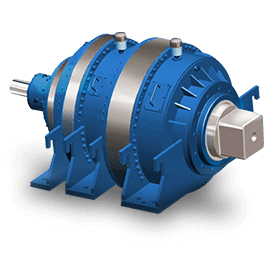 Modular Planetary Gearbox
 Modular Planetary Gearbox
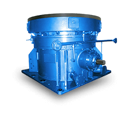 Special Planetary
 Special Planetary
FAQs
Planetary gears refers to a system of gears that consists of three main components: the sun gear, ring gear, and two or more planet gears. The sun gear is located at the center, the ring gear is the outermost gear, and the planet gears are the gears surrounding the sun gear and are inside the ring gear.
What data are required to be furnished for selection of a Planetary Gearbox?
The following information needs to be given in your enquiry for selection of suitable size of a worm gearbox.
- Type of prime mover
- Horsepower of prime mover
- Output torque required from driven member
- Input speed of gear unit
- Output speed of gear unit
- Configuration of drive required and shaft disposition.
- Total daily hours of running. If running is intermittent, details of duty cycle should be given. Particulars of any abnormal starting load should be stated.
- Details of reversing or shock loads.
- Details of any external loads imposed on gear unit.
- Details of any abnormal operating conditions, e.g. ambient temperature, humidity, etc.
The following information needs to be given in your enquiry for selection of suitable size of a planetary gearbox:
- Type of prime mover
- Horsepower of prime mover
- Output torque required from driven member
- Input speed of gear unit
- Output speed of gear unit
- Configuration of drive required and shaft disposition.
- Total daily hours of running. If running is intermittent, details of duty cycle should be given.
- Particulars of any abnormal starting load
- Details of reversing or shock loads.
- Details of any external loads imposed on gear unit.
- Details of any abnormal operating conditions, e.g. ambient temperature, humidity, etc.
The mechanical service factor for a gearbox is decided based on following parameters.
- – Prime Mover – Electric Motor, IC engines, etc.,
- – Duration of service hours per day
- – Type of load – uniform, moderate, heavy based on the application
The thermal service factor is based on following 2 parameters.
- – Ambient temperature
- – Running time in any hour.
- The following are the advantages of planetary gearbox:
- – High reduction ratio
- – Compact in size – low space requirement
- – High overall efficiency
- – High torque to weight ratio
- – High reliability
- – Long service life
- – Good starting performance under load
- – Fully reversible
The standard maximum allowable oil sump temperature is 95°C as per ANSI/AGMA standard. It must be recognized that operating above 95°C may reduce lubricant and contact seal life and increase the surface deterioration on the gears and bearings with a subsequent increase in the frequency of maintenance.
The maximum allowable vibration limit for a gear reducer is 4.5 mm/sec.
The maximum allowable vibration limit for a gear reducer is 85 dB at a distance of 1 meter.
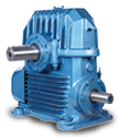
 Parallel Shaft Geared Motor
 Parallel Shaft Geared Motor
 Co-axial Shaft Geared Motor
 Co-axial Shaft Geared Motor
 Bevel Helical Geared Motor
 Bevel Helical Geared Motor
FAQs
The class of gears in geared motors is DIN class 7.
Taper Roller bearings are used on the output shaft.
Double Lip oil seals are used on the output side.
The maximum allowable noise level is 80 dB at a distance of 1 meter.
The oil grade to be used is VG 220.
 Variable Speed
 Variable Speed
 Constant Speed
 Constant Speed
FAQs
FP/DFP type couplings are called as Runner Drive Coupling as ‘runner’ with shaft is directly connected to ‘motor shaft’.
183°C temperature is allowed in FCU type coupling due to mechanical seal arrangement.
Power/Torque is transmitted gradually from motor to driven machine in a smoother manner. Thereby, a soft start is given to the machine. When stalling takes place at machine end, the output speed of secondary parts get reduced, thereby oil is churned within the working circuit which results in temperature rise and fusible plug blow off / oil escape from the coupling. Hence, no power transmission and a motor is protected from overloading.
The following are the parameters that are required for the selection of a fluid coupling - motor kW, speed, demand power, application details, mounting, shaft details of both sides, type of duty and required accessories.
Direct drive mechanical couplings require motors that are two times the normal size to overcome the inertial load, which are expensive. Whereas, based on the demand for power of the machine, fluid coupling and electric motor is selected which is 10-15 % more than actual power requirement. Hence, initial investment in motors is less and drive becomes economical/cheaper than direct couplings.
Mineral oil of VG 46 properties and mixture of water and Lub for underground applications.
Oil quantity of working circuit is controlled by scoop tube operation, either by feeding the oil quantity or removing the oil quantity to obtain the variable speed/torque at output end.
Leak off nozzle, CQEV and DQEV
Power saving is compared with direct/damper drive and fluid drive couplings. During fluid coupling speed variation, consume power and also the losses across fluid couplings are considered for motor shaft power computation. Whereas, the power consumed in other drives are more than fluid coupling. Hence, the difference of these values is taken into account for power saving calculation.
Temp switch / Temp gauge / Pressure gauge/ Pressure switch - are normally supplied in PST type fluid coupling. Flexibly connecting at both ends, the actuator for speed variation, cooling system (water/air operated), control panel, etc accessories are also supplied.
SCR type coupling is a self-pumping type of fluid coupling as it does not require a pump for oil circulation. In SCR coupling, scoop tube feeds the oil into the working circuit.
PST type coupling requires oil circulation pump (INT/EXT type) and the scoop tube to remove the oil from the working circuit. SCR coupling rotates at motor speed with oil reservoir whereas PST type coupling has stationary housing in which rotating body is enclosed for safe operation.
In PSV type fluid coupling, solenoid valve is used for flow control/division. Hence, PSV coupling doesn’t have a scoop tube.